CAx Interoperability Forum
CAx Domain Overview
The Computer-Aided-“x” (Design, Manufacturing, Inspection) Implementor Forum (CAx-IF) is a sub-group of the MBx-IF dedicated to the implementation and testing of the STEP AP242 (“Managed Model-based 3D Engineering”) standard in the Mechanical CAD domain.
This includes 3D geometry as precise B-Rep as well as Tessellated Geometry, Product and Manufacturing Information (PMI), Kinematic Mechanism and Motion, Composite Materials, User Defined Attributes, Validation Properties, and more.
Mechanical CAD
The 3D Mechanical domain covers the definition of the physical shape of a component, the positioning of components within an assembly, and the information about shape, such as tolerances or surface finish, which constrains the results of a manufacturing process, but does not specify the process itself.
The Domain also covers the ‘explicit representation’ which refers to the mathematical representation of the final result of the CAD model. From the designer’s point of view, it corresponds to the 3D shape (points, curves, surfaces, solids etc.). Explicit 3D shape may be associated with non-geometric data including design management meta-data such as layer, color or group or user defined properties. These non-geometric data are optional, and are added by users and checked and validated by specific tools.
Product & Manufacturing Information (PMI)
Following industry requirements, PMI were initially represented graphically as as non-semantic Polylines aimed at human consumption, e.g., for display in a 3D viewing application. This includes the “cross-highlighting” capability, where selecting an annotation also highlights the underlying geometry affected by the PMI, as well as the definition of Saved Views according to ISO 16792 or ASME Y14.41.
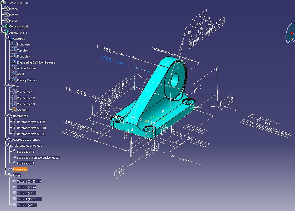
Semantic representation is the next level of PMI data transfer, aimed at automated consumption by other software tools. These might be other CAD systems, for instance at a supplier, or downstream applications such as inspection or manufacturing planning tools. The goal is to reduce, ideally avoid, the need to manually re-enter any information, thus increasing process efficiency while reducing the risk for errors.
Finally, PMI also encompasses manufacturing features in human-readable and computer-interpretable formats. This includes machining features, the representation and presentation of holes and fasteners, mechanical installation, and assembly joints.
Persistent IDs and Traceability
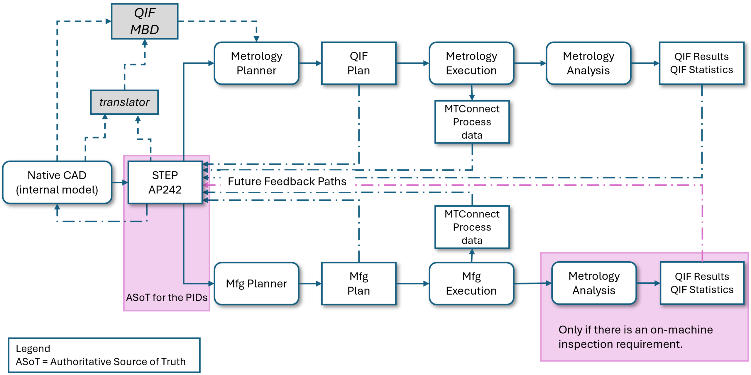
In the era of Model-Based Definition (MBD), establishing seamless traceability from design intent through manufacturing to quality inspection has become essential. Traditional manufacturing workflows often break the connection between design specifications and inspection results. When a part fails inspection, engineers struggle to trace the failure back to specific design requirements.
This challenge is addressed by implementing Persistent Identifiers (UUIDs) that maintain identity across system boundaries, as documented in the “Recommended Practices for Cross-Domain Exchange for Downstream Uses“, jointly published by DMSC and the CAx-IF.
The STEP standard uses V5_UUID_ATTRIBUTE (namespace-based, repeatable UUIDs) to tag geometric entities and PMI elements. QIF files preserve these identities through EntityExternalIds, creating a robust linkage mechanism that survives data translation between CAD, CAM, and CMM systems.
Research validated by CAx-IF testing demonstrated that Persistent ID-based traceability between STEP and QIF is achievable and practical. The combination of V5_UUID_ATTRIBUTE in STEP files and EntityExternalIds in QIF provides a robust, standards-compliant mechanism for maintaining the digital thread from design through inspection. With proper implementation following established rules and patterns, 100% traceability success is attainable, enabling true Model-Based Definition workflows where design intent flows seamlessly to quality verification.
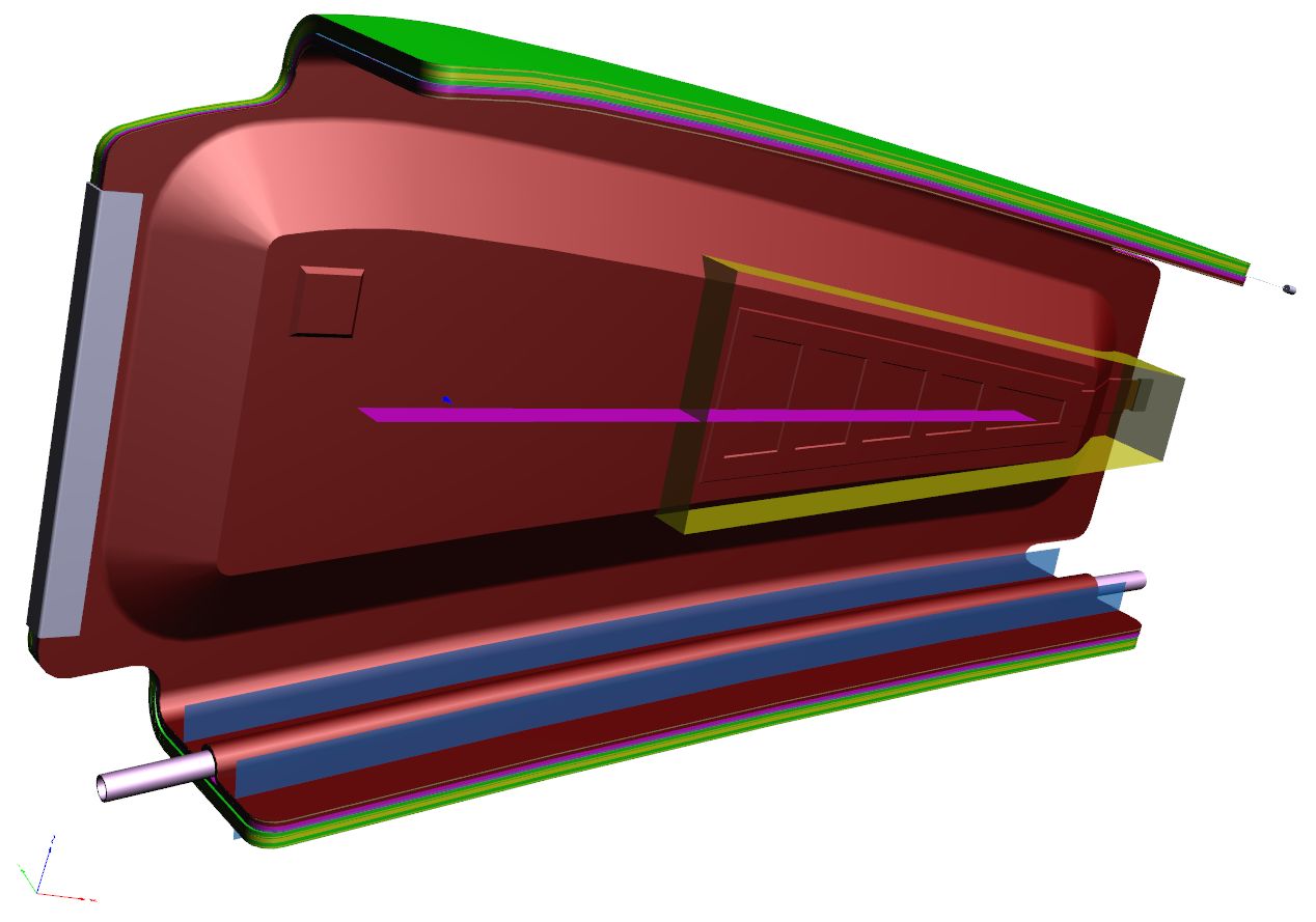
Composite Materials
The area of Composites Materials is focused on information such as:
- Sequences
- Plies
- Cores
- Material properties
- Rosette
- Orientation
The STEP AP242 standard also allows the transfer of CAD 3D tessellated solids for each composite ply. This development improves the visualization of the composite structures along with providing an unambiguous explicit representation of a composite part. This explicit 3D composite structure shape representation will also provide an unambiguous representation for purposes such as maintenance and bidding for manufacture.
Kinematics
Classically, the focus of Mechanical CAD is to ensure that the part can be manufactured correctly.
Products such as cars or planes are not static, however, and contain many moving components as well: engine, power windows, foldable roof, windshield wipers, cargo doors, etc. Thus, Kinematics are used to ensure they move correctly, and also to illustrate the behavior of the finished product.
The use cases range from the definition of the Kinematic Mechanism, providing all relationships and constraints between the elements so that their definition can be changed in the receiving application, to Kinematic Motion, which defines discrete positions of the components over time that can be played back like a movie.